.png)

Lift force- Understanding lift in a better way!
- Shalmali

- Jun 18, 2021
- 6 min read
Updated: Jul 2, 2021
The conclusion and end to Lift Force!
Table of Contents:

This is a continuation of the article "Lift Force - Aerodynamic Force Resolution", please do check it out before jumping into this one. Let's understand a few terminologies that are used in Lift Force.
Airfoil/Aerofoil
An airfoil is a term used to describe the cross-sectional shape of an object that, when moved through a fluid such as air, creates an aerodynamic force.
In other words, it is the cross-section of the wings of the aircraft. The following are terminologies used with respect to airfoil.

Leading-edge: It is the edge of the airfoil that comes in contact with the surrounding fluid first.
Trailing-edge: It is the edge of the airfoil that comes in contact with the surrounding fluid last.
Upper Surface / Upper camber: It is the airfoil surface to the upper side between the leading and trailing edge.
Lower Surface / Lower camber: It is the airfoil surface to the lower side between the leading and trailing edge.
Chord line: It is an imaginary line between the leading edge and the trailing edge.
Chord: It is the distance between the leading edge and the trailing edge along the chord line.
Mean camber line: It is a line joining the leading and trailing edges of an airfoil, equidistant from the upper and lower surfaces.
Maximum Camber: It is the maximum distance of the mean camber line from the chord line.
Maximum thickness: It is the maximum distance of the lower surface from the upper surface.
Types of Airfoil:


There are few types of airfoil and they are used as per the requirement and usability, As shown in the image above. Mainly there are two types: symmetrical and non-symmetrical airfoils.
Symmetrical airfoil: This has mirrored upper and lower surfaces such that the chord line and mean camber line are the same producing no life at zero AOA. These find applications in most of the light helicopters in their main rotor blades.
Non-symmetrical airfoil: It is also known as a cambered airfoil. This has different upper and lower surfaces such that the chord line is placed above with large curvature. These have different chord line and chamber line. The advantages of non-symmetrical airfoil is that the lift to drag ratio and stall characteristics are better and useful lift is produced at zero AOA. The disadvantages are that they are not economical and there is a production of undesirable moments.
The point where lift and drag forces acting on the airfoil. You can read here.
Angle of Attack (AOA):
It is the angle formed by the Chord line of the airfoil and the direction of the relative wind or the vector representing the relative motion between the aircraft and the atmosphere.

Angle of attack affects the lift and drag force generated, mainly lift force. Understanding this effect will be easier when we refer George Cayley's theorem for lift. This theorem suggests that
When the angle of attack is zero- Lift force is zero and Drag force is significant. One can imagine this situation as the vehicle moving horizontally with zero AOA. This case will never produce any Lift, because lift is a vertical component of Aerodynamic force. The vertical resolution (Lift force) of Aerodynamic force is zero and horizontal force resolution (Drag force) is significant.
When the angle of attack is less- Lift force and Drag force increases. One can imagine this situation as the vehicle moving at a small angle to the horizontal datum with a small AOA. In this case, both lift and drag will be produced. The vertical resolution of Aerodynamic force and horizontal force resolution both are significant. As the AOA increases, the lift and drag force both increase.
When the angle of attack is more- The drag force goes on increasing but the lift force as you can see in the figure below start to decrease at a point, this is called as stall.
Stalling
Stalling occurs when angle of attack of an airfoil exceeds the maximum lift generation point.
It occurs when the angle of attack increases more than approximately 15 to 20 degrees, which may vary according to the fluid. As you can see in the diagram above when AOA increases, the boundary layer is separated. Which gives rise to increase in drag force and formation of wake. Due to stalling, not only fuel consumption is increased but also an aircraft may loose its control. Hence, it is important to control angle of attack in the rightly.
Aspect Ratio
Aspect ratio is the ratio of its span to its chord.


Span is the wings length from tip to tip or the length of rectangle. Chord is the height of the aircraft or width of rectangle. But in reality the aircraft is not a rectangle. Hence aspect ratio is calculated as the ratio of square of span to the area.

The longer are the wing higher is the aspect ratio. The aircrafts with high aspect ratio experience less of Drag force. The aircrafts with lower aspect ratio experience lower bending moment (which means they are stronger) and can roll easily.
Wing Tip / Winglet
Wing tip / Winglet is the end tip of wing of an aircraft. It plays a very important role in controlling lift and drag forces.
Winglets help to reduce drag and increase lift. They also increase the strength of the wings without increasing the span of the aircraft.

As we know that, the region below airfoil is at a higher pressure than the region above. At the tip of the wing there will be sudden mixture of the air at different pressure which will create a disturbance in the air flow leading to vortex. This is called as wingtip vortex. In absence of winglet, there is a lot of drag force generated.
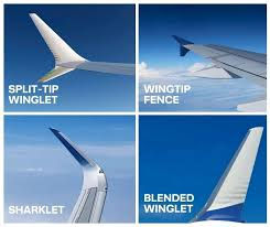

During takeoff and landing, and cruising at high altitudes, the angle of attack is high. In these cases the winglets prove to be of great support as they make the wings stronger. There are few types of winglets which are used for different applications according to the designer.
The dream of human flight must have begun with observation of birds soaring through the sky. The story of the invention of the airplane begins in the 16th, 17th, and 18th centuries, with the first serious research into aerodynamics. Leonardo da Vinci and Galileo Galilei in Italy, Christiaan Huygens in the Netherlands, and Isaac Newton in England all contributed to an understanding of the relationship between resistance (drag) and such factors as the surface area of an object exposed to the stream and the density of a fluid. Swiss mathematicians Daniel Bernoulli and Leonhard Euler and British engineer John Smeaton explained the relationship between pressure and velocity and provided information that enabled a later generation of engineers to calculate aerodynamic forces.
George Cayley, an English baronet, bridged the gap between physical theory, engineering research, and the age-old dream of flight. He gathered critical aerodynamic data of value in the design of winged aircraft, using instruments developed in the 18th century for research into ballistics. Cayley was also a pioneer of aircraft design, explaining that a successful flying machine would have separate systems for lift, propulsion, and control. While he did produce designs for ornithopters, he was the first experimenter to focus on fixed-wing aircraft. Shivkar Bapuji Talpade was an Indian instructor for aviation group back in 1890's in Sir J J School of arts and it is believed that he was successful in flying the aircraft in 1895 before Wright brothers did it, but because of lack evidence available his success didn't make lot of noise.
Magnus Effect
The Magnus effect is an observable phenomenon that is commonly associated with a spinning object moving through air or another fluid.
You might have observed 'Banana Shoot' in football. Ever wondered how that happens?
A spinning object in motion exerts a net force on the air, which according to Newton's 3rd law exerts an equal and opposite force back on the moving and spinning object, altering its trajectory. As we have seen earlier the asymmetry in the pressure distribution leads to the lift force, now when an object starts rotating this asymmetry also changes it's position leading to generation of force which changes the trajectory of the (rotating) object. This effect was first observed by a Heinrich Gustav Magnus that why known as "Magnus Effect", in case of a rotating cylinder.

Now the real question is does this affect lift force in aircraft? Yes! It does affect aircraft and it can affect its trajectory, roll, pitch and yawing.
Summary

An airfoil is a term used to describe the cross-sectional shape of an object that, when moved through a fluid such as air, creates an aerodynamic force.
Angle of Attack is the angle formed by the Chord line of the airfoil and the direction of the relative wind or the vector representing the relative motion between the aircraft and the atmosphere.
Aspect ratio is the ratio of its span to its chord.
Winglets help to reduce drag and increase lift.
Thank you everyone for giving such a huge response for the Lift and Drag forces posted before. As requested we have included the topic Magnus Effect too! We hope we have completed few more topics on Lift Force. Keep supporting us!


In stead of saying that "when angle of attack is less, lift and drag increases", Say when Angle of attack is Small, or low. The word "less' is comparative and therefore, implies that it was greater before, but you start with zero, so being less is confusing. It goes from zero to small amounts.